The contest administrator is not aware of any translators from Bookshelf to other file formats. In addition, the administrator cannot provide such translators.
No. For this contest cell flipping / mirroring / rotation is not allowed. All cells will be assumed to be in their default orientation.
During placement, for each non-rectangular node, you need to use the constituent shapes in the "circuit.shapes" file to determine the overlapping bins, and adjust their density, etc. In addition, for overlap calculation (legality checking) you should use the constituent shapes of the node. For routing, the routing blockage section in "circuit.route" file gives all the nodes that serve as blockages. Quite a few of them are non-rectangular nodes. For those nodes you need to use the constituent shapes in the "circuit.shapes" file to figure out the tile overlap and associated edge capacities.
Sitewidth refers to the width of a "placement" site, and Sitespacing refers to the spacing between adjacent "placement" sites. Please note Sitespacing does not refer to the minimum space between adjacent standard-cells. In other words, two standard-cells can abut with each other. But the lower-left X-coordinate (or left boundary) of every standard-cell must be placed on a location that is a multiple of the Sitespacing. Please refer to the figure below for a legal placement.

Siteorient and Sitesymmetry are used to specify the orientation of the standard-cells. For the contest no flipping or rotation is allowed. All cells will need to be placed in their default orientation. Hence, you do not have to consider these two parameters.
All macros and standard-cells should be aligned to the circuit rows. In other words, the lower-left Y-coordinate (or bottom boundary) of the macro or standard-cell should align to the bottom edge of a circuit row. Refer to the dac2012_check_legality script for more information.
The benchmark format follows the convention laid out in the ISPD 2008 routing contest. Essentially, for each tile edge, the "VerticalCapacity" or "HorizontalCapacity" values per layer give a measure of the total available space per tile edge. They are not the total number of global routing tracks per tile edge. Hence, if the capacity for a particular layer is 80, and the minimum wire width and spacing are both 1, this corresponds to 80 / (1+1) = 40 minimum width tracks per tile edge.
For the following configuration:
  VerticalCapacity   :  0  80   0  80   0  80   0  80   0

  HorizontalCapacity :  0   0  80   0  80   0  80   0  80

  MinWireWidth       :  1   1   1   1   2   2   2   4   4

  MinWireSpacing     :  1   1   1   1   2   2   2   4   4
Number of global routing tracks per tile edge:
  M1:     0/(1+1) =  0

  M2-M4: 80/(1+1) = 40  (for whichever capacity is not zero)

  M5-M7: 80/(2+2) = 20  (for whichever capacity is not zero)

  M8-M9: 80/(4+4) = 10  (for whichever capacity is not zero)
The maximum (default) routing capacity of a tile is not related to the tile width or height in any manner.
For any node that does not appear in the circuit.route file (under the Terminal_NI section), all its pins should be considered to be on M1 (default).
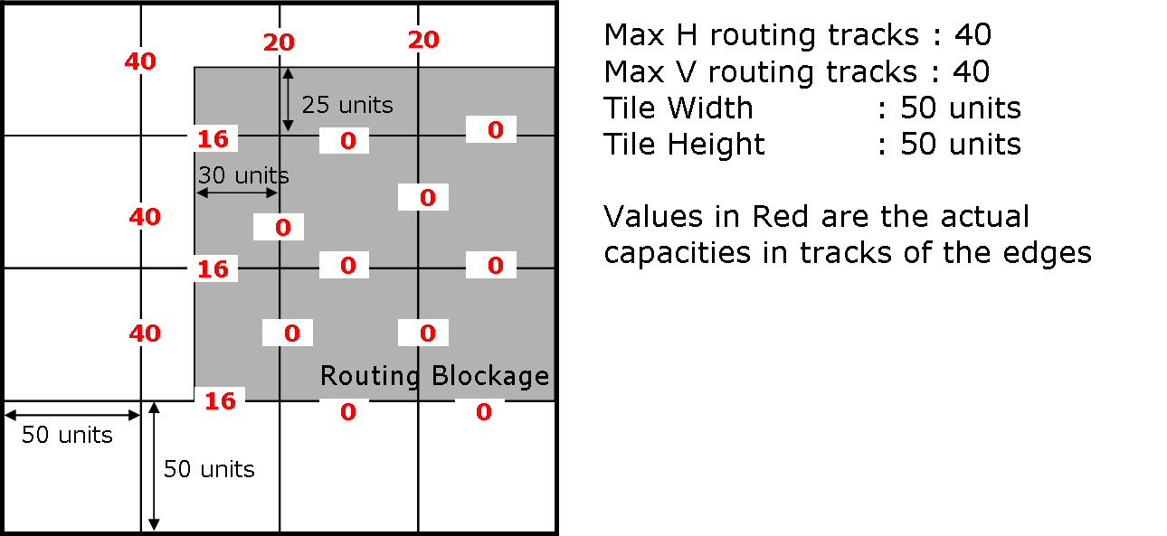
If multiple blockages intersect/overlap with a tile edge, then the capacity of the edge should reflect the total space blocked by all the blockages.
The following figure gives a detailed description of the blockage map construction (tile edge capacity adjustment):

The pin-offsets in the "circuit.nets" file are not in terms of the number of tiles/bins. They are absolute values from the center of the node. You should just add them to the node center to get the pin coordinates.
